Why do some aircraft have upturned wingtips?
Through the window, the wing seems to end in a small fin pointing toward the sky. That winglet reshapes airflow near the tip to reduce some of the drag associated with producing lift. It does not erase the aircraft's vortices, and its benefit depends on the wing and the conditions it was designed for.
Look at how the tip joins the wing
Next time you can see a wing, notice one detail: does the end rise abruptly, curve smoothly upward, or split into upper and lower parts? There is more than one way to make a wingtip device. Its connection to the main wing is part of the design, not just a styling choice.
You do not need to identify the aircraft from a silhouette. Start with the question the shape poses: why put another surface here, at the far end of the wing? NASA Glenn's introduction to winglets emphasizes that they must be integrated with the whole wing. A shape that helps one design is not automatically an improvement for another.
Air moves around the end
A lifting wing turns the surrounding airflow and develops a pressure distribution that supports the aircraft. In the familiar case, pressure above the wing is lower than pressure below it. Near a real wing's tips, air can move around the end from the higher-pressure region toward the lower-pressure region.
That gives the flow a sideways and turning motion as well as its motion past the aircraft. Behind the wing, the flow rolls into a wake that includes a pair of counter-rotating vortices. These are movements of air, not permanent white lines. They can exist without being visible.
NASA's explanation of induced drag connects this three-dimensional flow to the aerodynamic force on the wing. The useful picture is not air catching on a sharp corner. It is a finite wing producing lift while setting a substantial region of air in motion.
Supporting the aircraft has a drag cost
The flow behind a lifting wing includes a downward component, often called downwash. Its effect on the flow experienced by the wing gives the aerodynamic force an additional rearward component. That component is induced drag, also called drag due to lift.
The aircraft also encounters other forms of drag, including skin friction. So a reduction in induced drag is not automatically the same percentage reduction in total aircraft drag, let alone fuel used on an entire trip. Those are different quantities with different conditions attached.
Follow the tip flow and the force directions in the diagram
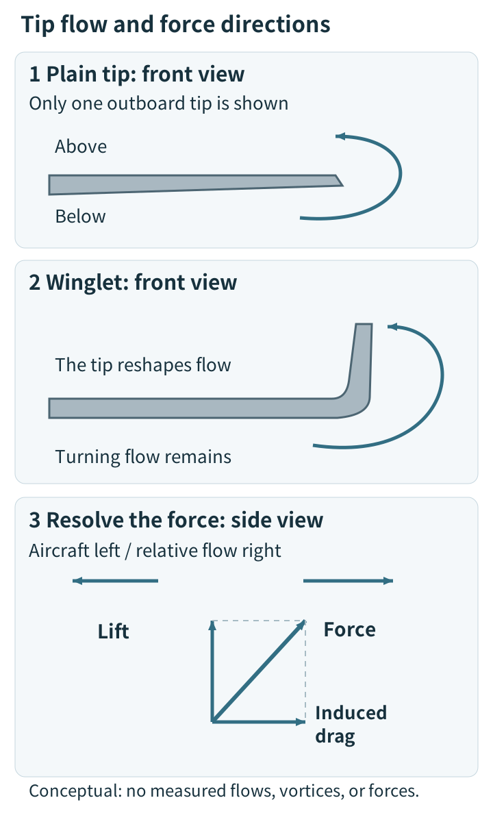
The upper panels are original conceptual sketches. Curving airflow remains in the winglet panel. The lower panel separates upward support from a rearward drag component; arrow lengths are not measured forces. The picture is not a computational flow simulation or a comparison of actual vortex strengths.
A small wing, rather than a sealed wall
A winglet is itself an aerodynamic surface. Its height, angle, section, and connection to the main wing help determine how it interacts with the local flow and changes the wing's loading. It is not simply a fence that traps every bit of air underneath.
A successful design reduces induced drag while the aircraft still leaves a vortical wake. A winglet therefore does not make the air behind an aircraft harmless or remove the need for wake precautions. Looking at the tip alone cannot establish the strength of that wake.
The engineering problem also includes the forces carried by the structure. Richard Whitcomb's 1976 NASA technical report summary describes measurements of forces, moments, and loads, and a comparison with a horizontal wingtip extension at approximately the same increase in wing-root bending moment. Even the early question was broader than whether a bent tip looked aerodynamically promising.
Why not make every wing longer?
For otherwise comparable conditions, a long, slender wing can reduce induced drag. Extending the span is therefore another design route. But wings have to fit into an aircraft's operating environment, including airport gate space, and their structure has to carry the added loads.
NASA's account of winglet development explains why span limits and structural weight made winglets attractive compared with simply extending some wings. This does not make a winglet a free addition. It adds surface area and weight, changes structural loads, and can require reinforcement. The complete balance matters.
The flight conditions matter, too. A design is evaluated for the aircraft's intended work, rather than for one photograph or an isolated tip. Comparing fuel use over a flight requires a defined aircraft, loading, and mission. A benefit measured under one set of conditions cannot be transferred unchanged to every route.
A bare-looking tip is not a verdict
An aircraft without an obvious vertical winglet may use span, wing shape, and tip geometry to achieve its intended performance in a different way. You cannot rank two aircraft's efficiency by checking whether their tips point upward. Nor can you establish their age or quality from that feature alone.
NASA's history of the KC-135 winglet flight tests describes a program that began in 1979. It provides evidence that a particular winglet design could help a particular aircraft. Its reported results are not a universal fuel-saving percentage for today's airliners, so this article does not assign one.
Folding a paper airplane's tips can be an interesting experiment, but it is not a scaled fuel-economy test for a passenger jet. Size, speed, weight, shape, and stability differ. The lesson to carry from the window seat is simpler: that small surface belongs to a much larger design problem.
Notice the tip, then imagine the invisible flow around and behind the wing. The aircraft must move air to support itself. A carefully designed winglet can help it do that job with less drag, within the compromises of the whole aircraft.